DDS Arduino AD9850 Hans Harbeck´s homepage
Introduction AD9850/AD9851 DDS module is based on DDS IC AD9850/AD9851 produced by ATI company. It is used to make sine wave and square wave of different frequencies and you can control the module for different frequency output by either serial mode or parallel mode on board.
AD9850 DDS Function Signal Generator Module Compatible with 9851 for DIY Arduino Free Shipping
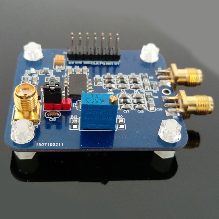
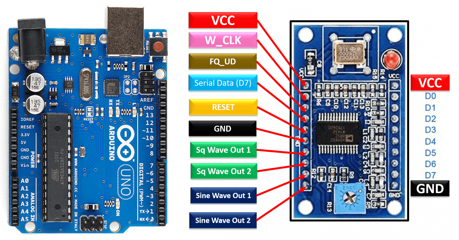
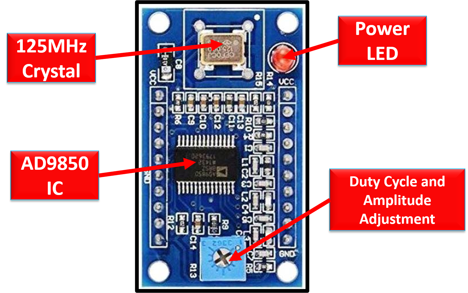
The AD9850 DDS Signal Generator Module includes a DSS synthesizer, a 125MHz oscillator to provide clock and timing control for the integrated circuit, and an AD9850 IC to handle all processing. The module is equipped with an internal potentiometer that can be used to change the pulse lengths and offset of the signals. Pinouts Hardware Required

JA2GQP’s Blog Arduino AD9850 DDS VFO Ver.1.2
In this Tutorial we will learn how to make a Frequency Signal Generator using a AD9850 module and Arduino.Full tutorial: https://www.instructables.com/How-to.
AD9850 DDS with ARDUINO
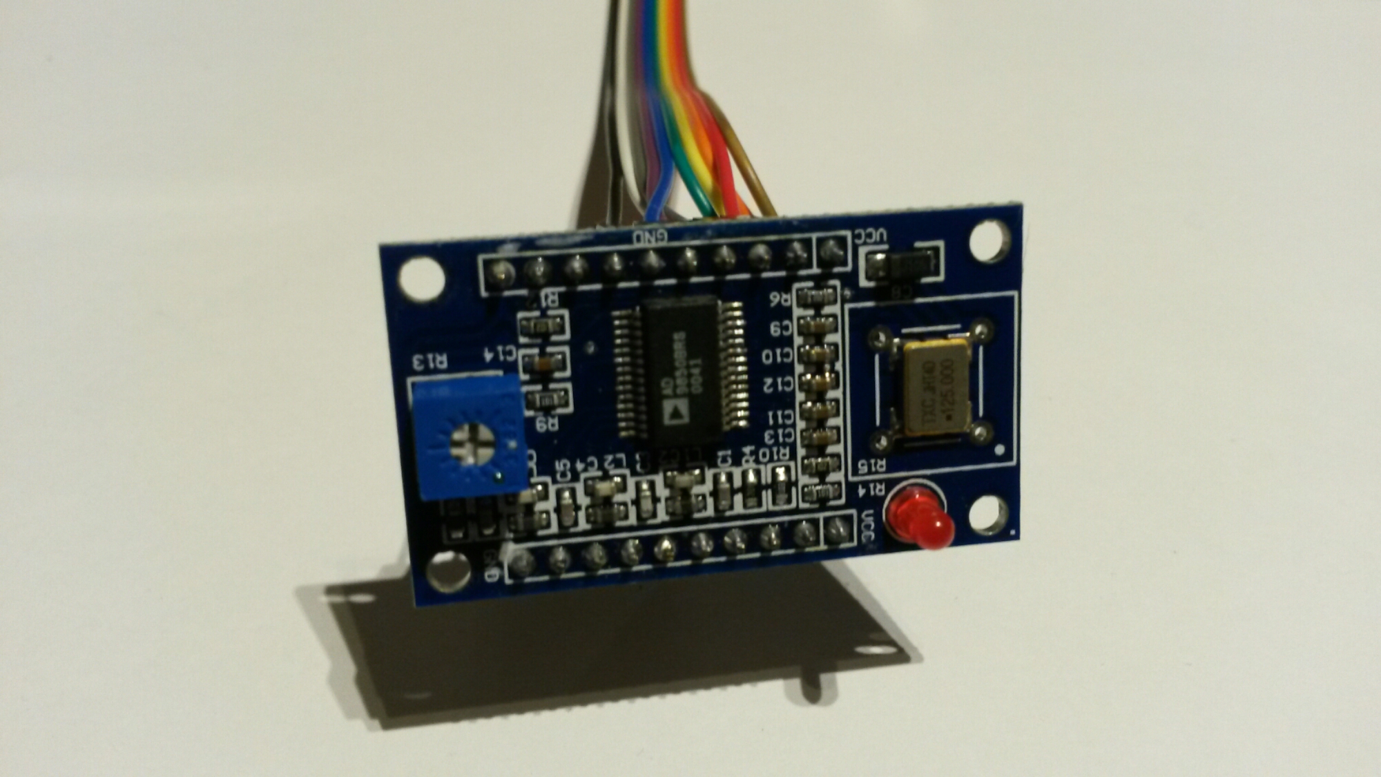
Actually, the DDS chip AD9850 uses the rare LSBFIRST mode in the SPI protocol, but that is the only difficulty. The hardware could not be done easier: just three wires plus power connections between the NANO and the HC-SR08. Please note that two wires are hidden under the Arduino NANO. The code below produces a sweep from 1 Hz to 40 MHz which.
cheap AD9850 DDS synthesizer project
An Precesion Signal generator is very easy and affordable make using an arduino and dds synthesizer (ad9850) . Its World's first smallest portable signal gen.
AD9850 DDS Signal Generator Pinout, Interfacing with Arduino, Features
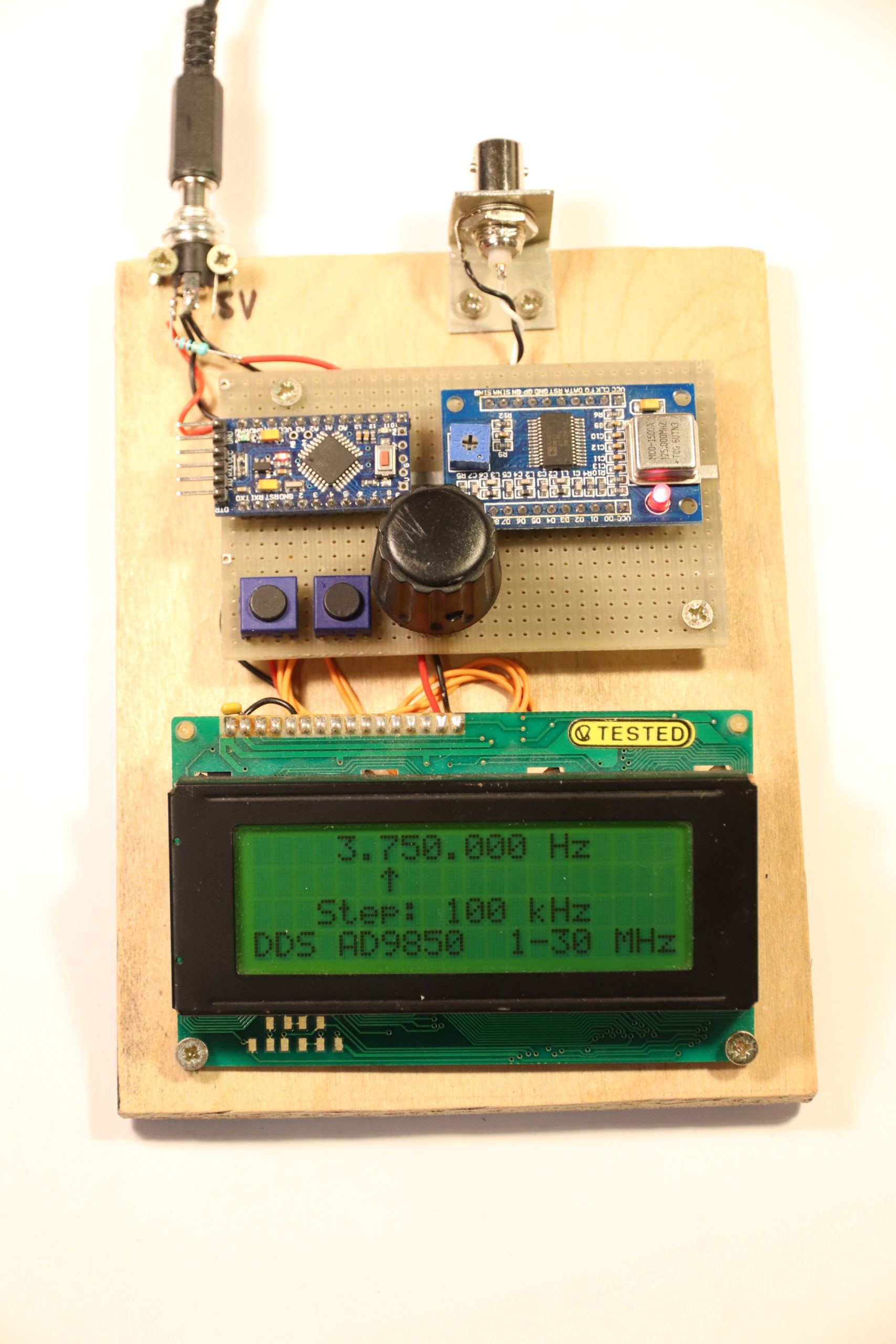
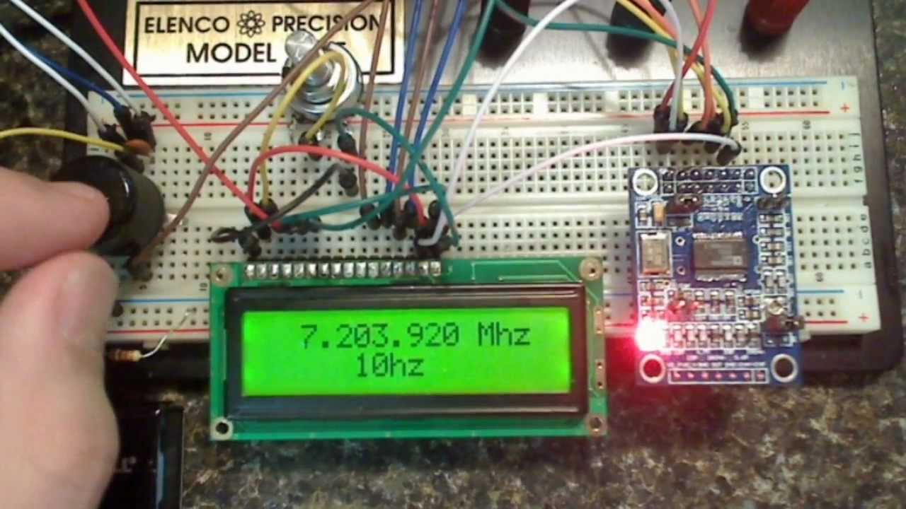
AD9850 works on dds (direct digital synthesis ) which can generate analog waveforms with digital input , here i used arduino pro mini to control dds board and Hitachi hd 44780 lcd display (16×2 lcd) to display current frequency and chage steps. This signal generator runs on USB 5V and consumes 270 ma max !
Testing an AD9850 DDS module
Interface AD9850 DDS Signal Generator Module with Arduino - Generate Waveforms AD9850 DDS Signal Generator Module is one of the small, low-cost boards to generate analog signals. This integrated board can be controlled through a microcontroller and can be digitally programmed using Direct Digital Synthesis Technology (DSS).

Arduino oraz generator sygnału DDS AD9850 40 MHz Botland Robotic Shop
In this Tutorial we will learn how to make a Frequency Signal Generator using a AD9850 module and Arduino. Watch the Video! Note: I managed to get frequency up to +50MHz but the signal quality gets worse with the higher frequencies. Ask Question Step 1: What You Will Need Arduino Uno or any other Arduino board AD9850 (DDS Synthesizer) More Info

AD9850 DDS Module OLED Display The Smell of Molten Projects in the Morning
In Visuino, at the bottom click on the "Build" Tab, make sure the correct port is selected, then click on the "Compile/Build and Upload" button.Step 10: Play. If you power the Arduino module, The OLED Display will show the increasing Frequency. If you have an Oscilloscope you can connect it to the AD9850 SQ Wave 1 pin (see wiring schematic) or AD9850 Sine Wave 1 pin (see wiring schematic).
7mhz DDS VFO using AD9850 and Arduino Uno R3 YouTube
ERASynth is a high quality portable signal generator at a price point affordable by everyone including makers, students, universities, research labs, and start-ups. RF signal generators are expensive pieces of test equipment typically only accessible by pro engineers. ERASynth removes the cost barriers and makes quality RF signal synthesis.

Arduino DDS Frequency Signal Generator AD9850 YouTube
Using an Arduino to drive an AD9850 Direct Digital Synthesiser Module as an HF variable frequency oscillator. Contents0:00 Introduction0:33 The AD98500:46 Pl.

Dds Ad9850 arduino pro mini Dds, Arduino, Electronic products
The AD9850 is a chip that can produce a sinusoidal wave from about 1hz to 40mhz. Somehow the electronics dealers in Hong Kong have been able to mate the chip to a small board that provides TTL level control and then sell it for an unbelievable $8 (or less!). I know a few people have paid as little as $4 (USD) for them.
AD9850 DDS Signal Generator Pinout, Interfacing with Arduino, Features
4 commits Failed to load latest commit information. DDS-AD9850.ino LICENSE.md README.md eq.gif README.md Arduino sketch for DDS AD9850 Simple arduino sketch for driving DDS AD9850 Analog Devices AD9850 This little sketch is useful for driving the cheap Analog Device DDS AD9850.
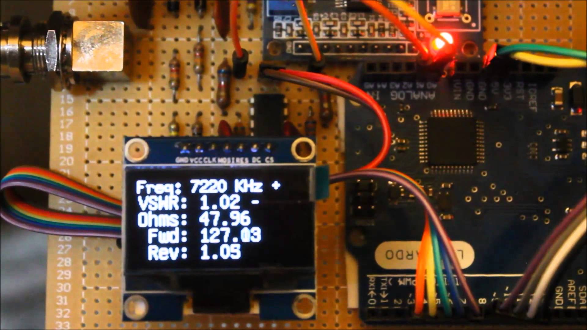
Arduino DDS AD9850 Antenna Analyzer
eSavera 2.69K subscribers Subscribe 6.5K views 3 years ago This tutorial has been designed to explain the interfacing of the HC-SR08 module to Arduino UNO. HC-SR08 module employs the AD9850.

JA2NKD's Arduino controlled AD9850 DDS VFO - JH8SST/7 YouTube
The AD9851 DDS board is shown connected to an Arduino in Figure 2. The Arduino is used to set the DDS output frequency. A DC block, the Picotest J2130A (shown in the figure, www.picotest.com) or the P2130A 500Hz - 8GHz Blocker, is used to connect the DDS output to a 50Ω oscilloscope port to view the spectral response.

Arduino + DDS AD9850 + LED + LCD I2C YouTube
AD9850 signal generator with arduino nano - Project Guidance - Arduino Forum AD9850 signal generator with arduino nano Using Arduino Project Guidance zer044 June 24, 2014, 4:33pm 1 Im trying to get the arduino to use this new AD9850 i have. I'm having difficulties trying to get a square wave output.
